Servo-Actuated-Bionic-Eyes
A pair of mechanically-driven eyes that pivot, rotate, and blink, mimicking the real motions of an eye following a face. ML embedded into mechanical systems.
<!--- This is an HTML comment in Markdown -->
<!--- Anything between these symbols will not render on the published site -->
| Engineer | School | Area of Interest | Grade |
|---|---|---|---|
| Leo N | Amador Valley | Mechanical Engineering | Incoming Freshman |
Replace the BlueStamp logo below with an image of yourself and your completed project. Follow the guide here if you need help.

Final Milestone
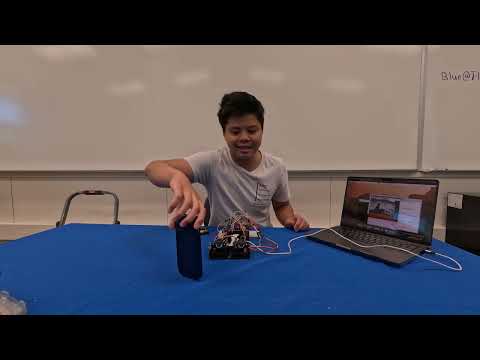
I went through three different open source CNN models (found on Edge Impulse) which were refined off of FOMO (Faster Objects More Objects), however these models were not accurate enough to maintain a realistic gaze. There are many factors, like lighting, resolution, etc that I cannot alter myself, so I had to pivot to an older, simpler, and more reliable CV model, Haar Cascade. I integrated my firmware into the mechanism wtih a clever solution that takes the centroids detected face and alters the horizontal by the deviation of the points compared to the face, which was also my biggest challenge. It was extremely tedious calibrating and fine-tuning the mechanics to achieve a realistic motion when paired with my firmware, especially because of the variability of both systems. However, watching my project come to life and mimic a real, biologic thing made the struggle worth it. I am thrilled with how my project turned out and some of the concepts I was able to learn like: properly powering electronics and taking into account current and voltage, integrating two unique systems, and how simpler CV models work in interpreting images. After BlueStamp, I hope to continue developing my design skills and make projects similar to this.
Second Milestone
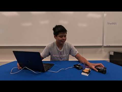
After four physical iterations of my design, I finally ended up with one I was satisfied with. My first few versions had a few unplanned additions, like for instance, washers between the eyelid screw joints that act like spacers in order to prevent friction between the two 3D parts. I had to use wood screws to tap the 3D printed holes for the M2 screws to thread at all, and at the end I realized that the eyelids could be smaller in order for the whole assembly to have a more realistic feel (although I left this challenge for later). I discovered numerous clearance and tolerance issues as apart of my first few assemblies, which were easy but tedious fixes. I was definitely caught off guard with the amount of time I would spend on the blinking motion (around 2-3 days) in which I went through a lot of struggle. After a lot of tinkering with the 3D printed linkages I was planning to use, I came to the realization that I would have to use another design, which ultimately was the right choice. One of my favorite parts of this milestone’s period was when I fixed a recurring issue with a passive and simple solution. I was having trouble balancing the eyelids on the screw joints, in which they would slide or push each other off and ruin the blinking. I experimented with fastening washers to the ends of the joints when I found a novel solution which would indirectly fix the sliding. For the eyelid to slide off the joints, the opposite side of the lid joint part would have to have enough clearance to slide as well. If I could obstruct the other joint from moving towards the end of the joint, then I could inversely stop the sliding. Thus, I used two nuts on the ends of the joints as a way to passively fix the sliding. These types of satisfying solutions are why I find mechanical engineering so fascinating. My next steps will be integration my hardware with the software.
First Milestone
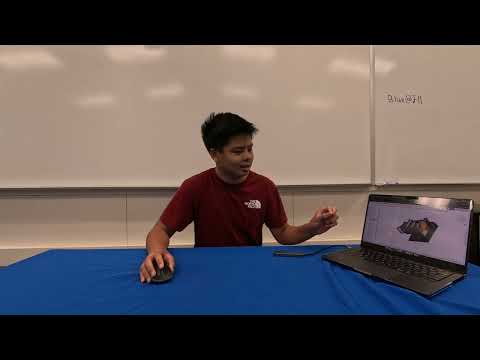
My project is a servo-driven system which imitates the human eye. The mechanism consists of a series of simple linkages which allow for pitch, roll, and blinking motions. Most of the parts were custom designs and 3D printed. They are joined by M2 and M3 screws, although wood screws may be needed to tap the screw holes. As of now, I have a complete assembly with all the necessary parts for a physical version of the model. I faced many challenges with the CAD. I went through three design iterations using different joints, like the universal joint. However, these designs were bulky and ineffective, so I pivoted to a ball-joint for the movement of the eyes. I created custom housing for the servos and balljoint, which led me to my second challenge, which was tolerances. It took a lot of prototyping to achieve a rigid or rotating relationship between two 3D printed parts with the printers at BlueStamp, and adjusting the assemblies once I had the tolerances figured out was a tedious and frustrating process. I also ran into clearance issues with my balljoints: Once I simulated the motions of my mechanism in the assembly, I realized I could not use a spherical eyeball in spherical eyelids. Instead, I pivoted to a mesh eyelid design that proivded clearance for the pitch and roll movements. Through this trial and error, I learned necessary skills in CAD, like how to properly assign joints in assemblies and how to work with mesh and curved bodies. I plan to complete a full physical version, revise my CAD in case of tolerance or clearance issues, and then experimenting with the integration of a vision model (either CNN or kNNs).
Schematics
CAD
CAD Prototypes
|
V1-1 - Universal Joint |
V1-2 - 3D Printable |
V2 - Ball Joint |
|
V2 - Ball Joint Assembly |
V2 - Ball Joint Eyelid Assembly |
V2 - Clearance Issue (1) |
|
V2 - Clearance Issue (2) |
V2 - Clearance Issue (3) |
Finished Assembly w/ Imported Parts
Wiring Schematics
As you can see, I powered the servos in parallel, boosting the current to around 6A at around 4-6 volts– there are also shared grounds between the MCU and power supply, and the jumpers are connected to the power rails of the breadboard.
Code
######remember sudo pigpiod to start daemon
from gpiozero import AngularServo
from gpiozero.pins.pigpio import PiGPIOFactory
from time import sleep
import cv2
from picamera2 import Picamera2
from threading import Thread
import random
factory = PiGPIOFactory()
singalPIN = 3
servo2 = AngularServo(singalPIN, min_angle=0, max_angle=180, min_pulse_width=0.0005, max_pulse_width=0.0025,pin_factory = factory)
singalPIN2 = 4
servo = AngularServo(singalPIN2, min_angle=0, max_angle=180, min_pulse_width=0.0005, max_pulse_width=0.0025,pin_factory = factory)
signalPIN3 = 2
servo3 = AngularServo(signalPIN3, min_angle=0, max_angle=180, min_pulse_width=0.0005, max_pulse_width=0.0025,pin_factory = factory)
sp2 = 17
sp1 = 27
sp3 = 22
servo4 = AngularServo(sp1, min_angle=0, max_angle=180, min_pulse_width=0.0005, max_pulse_width=0.0025,pin_factory = factory)
servo5 = AngularServo(sp2, min_angle=0, max_angle=180, min_pulse_width=0.0005, max_pulse_width=0.0025,pin_factory = factory)
servo6 = AngularServo(sp3, min_angle=0, max_angle=180, min_pulse_width=0.0005, max_pulse_width=0.0025,pin_factory = factory)

## CAMERA ANGLE 0-1

##HORI INIT
HMIN,HMAX = 110,150
DEF = 130
rightoff = 10
#init defaults
servo2.angle = DEF
servo3.angle=100
servo.angle = 80
servo4.angle = DEF+rightoff
servo6.angle = 110
##servo5 at default is okay

CASCADE_PATH = '/usr/share/opencv4/haarcascades/haarcascade_frontalface_alt2.xml'
face_cascade = cv2.CascadeClassifier(CASCADE_PATH)

if face_cascade.empty():
    print("ERROR: cascade failed to load")
    exit(1)

picam2 = Picamera2()
picam2.configure(picam2.create_video_configuration(
    main={"size": (640, 480), "format": "XRGB8888"}
))
picam2.start()

smoothed_x, smoothed_y = 0.5, 0.5
ALPHA = 0.3
last_target = None
lost_frames = 0
LOST_TIMEOUT = 100

##blink inits
def blinkThread():
    while True:
        print("blink")
        blinkTime = random.randint(1,4)
        servo3.angle = 55
        servo5.angle = 120
        sleep(0.15)
        servo3.angle = 80
        servo5.angle = 90
        sleep(blinkTime)
blinkthread = Thread(target = blinkThread,daemon = True)
blinkthread.start()
try:
    while True:
        frame = picam2.capture_array()[:, :, :3]
        display = cv2.cvtColor(frame, cv2.COLOR_RGB2BGR)
        gray = cv2.cvtColor(display, cv2.COLOR_BGR2GRAY)
        gray = cv2.equalizeHist(gray)
        faces = face_cascade.detectMultiScale(
            gray, scaleFactor=1.05, minNeighbors=4, minSize=(80, 80)
        )

        if len(faces) > 0:
            if last_target is None:
                x, y, w, h = max(faces, key=lambda f: f[2]*f[3])
            else:
                x, y, w, h = min(
                    faces,
                    key=lambda f: (f[0]+f[2]/2 - last_target[0])**2
                                + (f[1]+f[3]/2 - last_target[1])**2
                )

            cx, cy = x + w/2, y + h/2
            last_target = (cx, cy)
            lost_frames = 0
            target_x_norm = cx / display.shape[1]
            target_y_norm = cy / display.shape[0]
            smoothed_x = ALPHA * target_x_norm + (1 - ALPHA) * smoothed_x
            smoothed_y = ALPHA * target_y_norm + (1 - ALPHA) * smoothed_y
            horiScale= cx/640
            ## min + range*angle
            horiMove = 150 - horiScale*(HMAX-HMIN)
            servo2.angle = horiMove
            servo4.angle = horiMove+rightoff
            print(servo4.angle)
            cv2.rectangle(display, (x, y), (x+w, y+h), (0, 255, 0), 2)
            cv2.circle(display, (int(cx), int(cy)), 6, (0, 255, 255), -1)
        else:
            lost_frames += 1
            if lost_frames > LOST_TIMEOUT:
                last_target = None

        cv2.putText(display,
                    f"gaze: ({smoothed_x:.2f}, {smoothed_y:.2f})",
                    (10, 30), cv2.FONT_HERSHEY_SIMPLEX, 0.6, (255, 255, 255), 1)

        cv2.imshow("Face", display)

        if cv2.waitKey(1) & 0xFF == ord('q'):
            break
finally:
    picam2.stop()
    cv2.destroyAllWindows()
Bill of Materials
| Part | Note | Price | Link |
|---|---|---|---|
| Pi Zero 2W | MCU | $40.99 | Link |
| 2 MG90 servos | Drives mechanism | $8.88 | Link |
| Acrylic Eyeballs | Mock eyes for realisms | $7.99 | Link |
| Joystick | Manual control for mechanism | $6.99 | Link |
| Breadboard | Prototyping electronics | $6.83 | Link |
| M3 screws, bolts & nuts | Joining 3d printed parts together for a final product | $7.99 | Link |
| 6V - 4 AA battery supply | Power source for servos | $4.99 | Link |
| Perfboards | Final draft of electronics | $4.99 | Link |